Wikipedia

Search results

Sunday, December 29, 2013

المقاطع المعدنية المشكلة على البارد

:مقدمة

يوجد بشكل عام طريقتين أساسيتين في صناعة الفولاذ المستخدم في البناء الطريقة الأولى هي تشكيل الفولاذ على الساخن حيث يتم صهر الحديد وصبه بشكل بروفيلات معدنية لها إشكال ومقاطع محددة وفق مواصفات عالمية, أو يتم تشكيل الفولاذ على البارد بدون صهره وتسمى المقاطع الناتجة عن هذه الطريقة المقاطع المشكلة على البارد حيث يتم تشكيل هذه المقاطع من صفائح معدنية رقيقة تتراوح سماكتها 0.5 -5 mm عبر آلات مخصصة تسمى آلات الدرفلة وضمن درجة حرارة الغرفة.

تم استخدام المقاطع المشكلة على البارد في البناء بشكل فعلي في عام 1930 وتطور استخدامها مع تطور كودات البناء حتى أصبحت تستخدم بشكل واسع في يومنا هذا.

تطبيقات استخدام المقاطع المشكلة على البارد:

- في أسقف الأبنية الصناعية (الهنكارات) وأسقف الأبنية السكنية.

- في هياكل الإطارات الفراغية والإطارات المستوية.

- من أجل تثبيت التجهيزات الملحقة بالبناء.

- في منشآت سند التربة مثل (sheet pile).
- تستخدم كقوالب وتسليح للبلاطات المختلطة.

حيث يبين الشكل (1)، استخدام المقاطع المشكلة على البارد في الهنكارات المعدنية.


الشكل (1)، استخدام المقاطع المشكلة على البارد في الهنكارات المعدنية


الشكل (3)، استخدام المقاطع المشكلة على البارد في منشآت سند التربة

تتميز المقاطع المشكلة على البارد بما يلي:
- خفيفة الوزن (باستخدام المقاطع المشكلة على البارد يتم توفير حوالي (38-50%) من وزن المنشأ في حال استخدام تلك المشكلة على الساخن).
- ذات مقاومة عالية حيث أن الفولاذ المشكل على البارد يسلك سلوك مطاوع أكثر من الفولاذ المشكل على الساخن.
- سهولة الإنتاج.
- سهولة وسرعة التركيب.
- اقتصادية في النقل والحمل.
- مقاومة للاحتراق.
- لا تحتاج إلى قوالب في الإنشاء.
- تامين فراغات للتمديدات الميكانيكية في الأسقف المصنوعة من الصفائح المتموجة.
- يمكن تشكيل أي شكل يلاءم الضرورة المعماري عبر هذه المقاطع.

- أفضلية في دقة التنفيذ باستخدام هذه المقاطع عن المقاطع المشكلة على الساخن.

- مقاومة للتآكل والزحف بشكل أفضل من تلك المشكلة على الساخن.

- يمكن استعمال أي نوع من أنواع التثبيت لتثبيتها مثل اللحام والبراغي واللصق.

- يمكن إعادة تدويرها.

ومن الكودات والمنظمات التي تبحث في مجال المقاطع المشكلة على البارد:

American Iron and Steel Institute (AISI) 

Steel Framing Alliance (SFA) 

Steel Stud Manufacturers Association (SSMA) 
Cold-formed Steel Engineers Institute (CFSEI) 
Structural Stability Research Council (SSRC) 
Metal Building Manufactures Association (MBMA) 
Steel Joist Institute (SJI) 
Steel Deck Institute (SDI) 
Steel Recycling Institute


صناعة المقاطع المشكلة على البارد:
تملك المقاطع المشكلة على البارد مقاطع مضلعة ذات سماكة ثابتة على كامل المقطع كم يبين الشكل (4):


الشكل (4)، المقاطع المنوذجية المشكلة على البارد.
 ويتم صناعة هذه المقاطع إما بطريقة الثني (Floding) أو بطريقة (press backing) أو عبر آلة درفلة للصفائح المشكلة على البارد في حال المقاطع الكبيرة، كما يبين الشكل (75).


الشكل  (5)، صناعة المقاطع المشكلة على البارد بطريقة (Floding).


الشكل  (6)، صناعة المقاطع المشكلة على البارد بطريقة (press backing).


الشكل  (7)، صناعة المقاطع المشكلة على البارد بطريقة الدرفلة.
مواد المقاطع المشكلة على البارد:
يتم صناعة الصفائح المشكلة على البارد من صفائح ذات مقاومة عالية حيث تصنع من الفولاذ الإنشائي الذي يتراوح إجهاد الخضوع فيه من (Mpa 220 -350 )، كما أنه من الممكن استخدام الفولاذ عالي المقاومة ليصل إجهاد الخضوع إلى (500 Mpa) كما بيبن الشكل (8)، منحني الإجهاد تشوه للفولاذ الإنشائي لمستخدم في المقاطع المشكلة على البارد:


الشكل (8)، منحني الإجهاد- تشوه للفولاذ المشكل على البارد.

  تصنع المقاطع المشكلة على البارد بمقاطع متعارف عليها ذات أبعاد نظامية ويتم استخدام هذه المقاطع إما منفردة أو مركبة كما يمكن صنع أي شكل من المقاطع المشكلة على البارد بحسب الطلب ومن أشهر هذه المقاطع:
1- مقطع مجراة (Plain Channels):
يتم الدلالة لمقطع المجراة بالرمز (LC) كما يبين الشكل (9):


الشكل (9)- مقطع مجراة مشكل على البارد
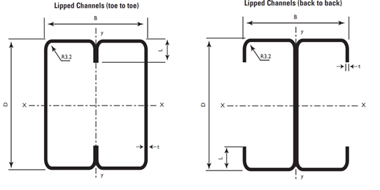
2- مقطع المجراة ذات الشفة (Lipped Channels):
يتم الدلالة لمقطع المجراة ذات الشفة بالرمز (LL) كما يبين الشكل (10).


الشكل (10)- مقطع مجراة ذو شفة مشكل على البارد.
3- مقطع الزاوية (Angle):
يتم الدلالة لمقطع الزاوية بالرمز (LA) كما يبين الشكل (11).


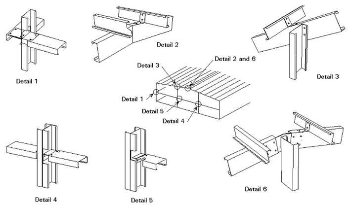
كما يمكن تجميع عدد من المقاطع المشكلة على البراد لتشكيل مقطع جديد كما تبين الشكل (12).


Saturday, August 17, 2013

Fire Protection For Steel Element

Fire Protection For Steel Element


-       There are four common methods of fire protecting structural steelwork;
-       Intumescent coatings
-       Board based systems
-       Sprayed fire protection systems
-       Concrete encasement or filling

Intumescent coatings:


Intumescent coatings may be brushed or sprayed onto steelwork rather like paint. The materials expand when subjected to fire and form an insulating foam. Intumescent coatings can achieve up to 120 minutes fire resistance, and are used mostly on exposed steelwork.

Board based systems:


Board based systems are used to form rectangular encasements around steel members, such as internal beams and columns.  Paint or other finishes can be applied directly to the boards. The level of fire resistance achieved depends upon the type and the thicknesses of the boards used and upon the method of attachment.

Sprayed fire protection systems:


Sprayed fire protection systems are usually based upon cementitious materials and are applied directly onto the surface of steelwork. They are generally low cost, but cannot receive finishes owing to their coarse uneven texture. Sprayed materials tend to be used where steelwork is concealed or where appearance is unimportant. Fire resistance is similar to that of board based materials.

Concrete encasement or filling:


Concrete Filled Structural Hollow Sections
Structural Hollow Sections (SHS) can be fire protected by filling with reinforced concrete. Concrete filled structural hollow sections can achieve 120 minutes fire resistance.
Slimdek®
The Slimdek® system has inherent fire resistance as the ASB section is encased in concrete with only the bottom flange exposed to fire. Without fire protection Slimdek® canachieve 60 minutes fire resistance.
Periods of fire resistance in excess of 120 minutes can be achieved if ASB is fire protected.
Multi-storey frames requiring 30-60 minutes can have 40% of the floor beams unprotected by following the recommendations of a special design guide.
Protection thicknesses
The section factor of a particular steel section is its surface area per unit length divided by its volume per unit length (A/V). This parameter defines how quickly a steel section will heat up when subjected to fire. The section factor for a member with box protection is lower than that for a member with profile protection, and hence box protected steelwork heats up more slowly and requires less protection.
Typical spray or board thicknesses for a column in a multi-storey building are as set out in the table below.
Fire resistance(minutes)
Profile Protection(mm)
Box Protection   (mm)
30
10
12
60
18
15
90
24
20
120
30
25


Typical spray or board thicknesses based on 254UC x 89 kg/m column in a multi-storey building.

Connections in trusses

Truss connections are generally welded, except for site splices.
The connections between the members of a truss were traditionally bolted but welded connections are now preferred, especially in tubular construction. Nevertheless it may be necessary to introduce splices in the chord members if the complete trusses are too long for transportation. These splices provide for bolting individual lengths of trusses on site and should be located and detailed carefully if they are architecturally important.
Connections in open section trusses are lapped and welded.
Traditional truss construction based on open sections (angles and tees) used bolts and gusset plates. The position of the bolts was usually detailed to minimise eccentricities. In welded construction the internal members are typically attached directly to the top and bottom chords. These chords are usually continuous except at changes of direction or where splices are necessary to reduce the length of the assembly for transportation. Internal members lap onto the chord members and are simply connected by fillet welding.
Connections in trusses using heavier sections are welded but may require more careful preparation.
Long span or heavily loaded trusses often use I, H or channel sections. Internal members are generally cut to fit directly against the flanges of the chord members and are profile welded to form the connection.
Connections in tubular trusses are usually welded.
Tube to tube joints, such as those in tubular trusses, are usually welded, because full profile welded joints not only look better but are also cheaper than creating elaborate bolted joints. It is usually cheaper to make truss connections if the chords are made from rectangular tubes, rather than circular. This is because the ends of the diagonals can be straight cut, rather than cut to the more complex intersection profile if circular chords are used. In either case the end of the diagonal may be cut in the same plane as the chords if a fillet weld is adequate. This will normally be adequate, but if a butt weld is needed the end of the diagonal must be properly prepared. A number of fabricators use profiling machines which automatically cut the diagonal to the correct line and end preparation for welding.
Welded connections for tubular trusses
Intersecting angles should not be too small.

It is important that the truss geometry does not produce too small an intersection angle between members. The limit is about 30 degrees for rectangular hollow sections and 20 degrees for circular hollow sections, and below this value it is difficult to get the welding electrode in to make a weld.